SPI Addressing
The SPI rack has 12 module slots which can house up to 12 modules. In most applications one slot is reserved for a controller module, either the C1 module or the combination of a C1b module with a C2 isolation box. These manage the communication between the host computer and the remaining 11 modules in the rack. This allows remote control of SPI modules. With few other applications all modules are operated directly from the front panel and a controller module may not be necessary. Even in such cases it may still be useful to equip the rack with a controller module, particularly the C2/C1b combination, to monitor the rack power supplies and temperature.
Addressing Non-Controller Modules
Modules in the SPI rack can be addressed by their unique address. This depends on the versions of the modules and of the rack hardware. On first-generation SPI racks and modules (a.k.a. SPI 1.0) there is no address setting in the rack chassis. The module address is determined within the module by a physical 4-bit jumper. On second-generation SPI racks (a.k.a. SPI 2.0) the rack chassis "suggests" a unique address to each slot, which will pass to an SPI 2.0 module in that slot. Below is a full explanation:
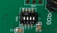
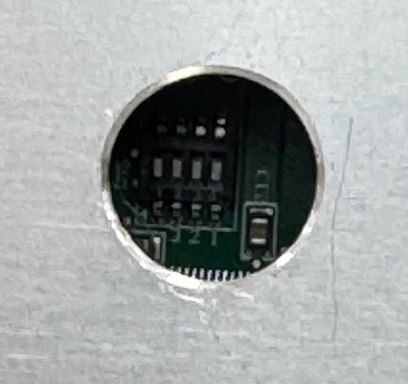
The picture above shows the jumper on an exposed circuit before it is fitted into the module frame. In most cases a drill hole is made in the frame to allow changing the jumper settings even on an encapsulated module.
Any module plugged into an SPI 1.0 rack will work based on its on-board jumper address since the SPI 1.0 chassis does not "offer" an address to the module. In this case SPI 2.0 modules as well will default to their on-board jumper address and behave like SPI 1.0 modules. Therefore it is advised to set the address jumper even for the newer modules.
In these racks every slot has a unique address "suggested" by the rack chassis. The address is a number from 1 to 12 which corresponds to its location in the rack box. The back plane inside the rack box shows the slot numbers, easily visible from the front side.
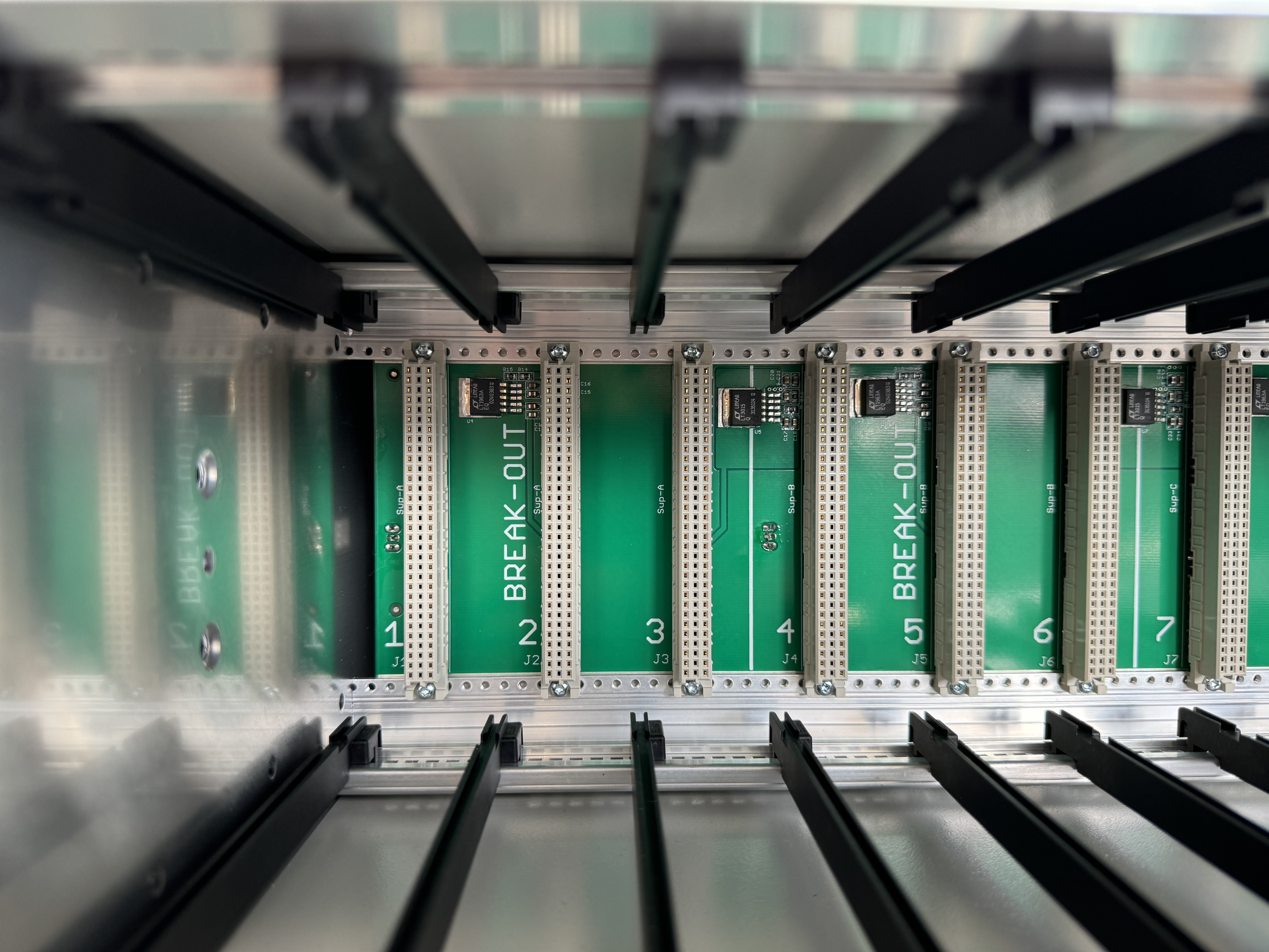
SPI 2.0 modules take advatnage of this "suggestion" and acquire their address from the slot location. This ensures no two modules have the same address.
An SPI 1.0 module in an SPI 2.0 rack will still use its on-board jumper address. This means SPI 1.0 modules in all cases take their address from their own on-board jumper.
Watch out for a potential case where SPI 1.0 and SPI 2.0 modules might be mixed in the same rack, where an address collision might still be possible. The best practice when working with SPI 1.0 modules is to plug them into the same slot as their jumper address. By catching that slot no SPI 2.0 module can acquire that address and conflicts are avoided.
To identify whether a module has SPI 1.0 or SPI 2.0 addressing:
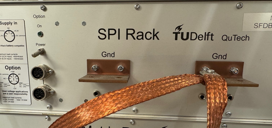
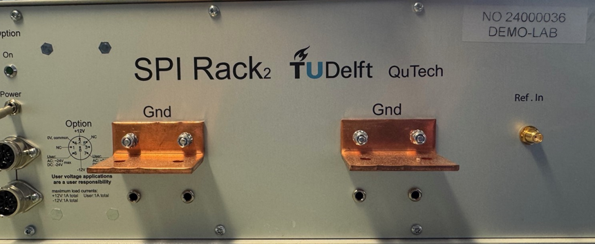
Check the product name: An SPI 2.0 rack is marked with a '2'. See the two images below.
Check its production date: Generally, modules built after Sept. 2021 are SPI 2.0 and capable of acquirng their address from the slot. The build date is coded in the serial number of the module, which is made the production year (2 digits), week (2 digits), and a running number (3 digits). For example 21-35-087 means the 87th unit of the type, built in August 2021.
Rack Addressing and Controller Module Addressing
Controller modules have different address rules: they are always addressed at address 0. Physically they can be placed at any position in the rack. Any controller module would work equally with first-generation and second-generation racks.
There are more enhanced versions of the controller modules, which allow to read a rack identifier number back to the host PC. The identifier number is settable by the user directly on the controller module via the same 4-pin jumper shown above. This jumper provides an "address" space of 0-15 for the rack address. Note that on the controller module this setting represents the "address" of the entire rack and not the controller address, since controller modules themselves are always set to address 0.
These enhanced controller modules are intended for set-ups which use multiple racks, helping the user identify the correct rack to control. Set-ups with multiple racks may be needed in case of exceeding the available 12 slots in a single rack or exceeding the battery capacity of a single rack (e,g, when using power-hungry modules such as S5k or D5b/D5c). It may also happen when separating DC/RF racks or isolated/non-isolated racks as part of the experimental set-up.
The enhanced controllers are available in both non-isolated and isolated versions: C1a replacing the non-isolating C1, and C1c replacing the isolating C1b.