S5t - 10MHz Sync Trigger

Description
The S5t is a module that generates triggers perfectly synced to the 10 MHz reference of the SPI Rack. It does this by dividing the reference in a microcontroller. The microcontroller clock is replaced by the 10 MHz reference and the internal hardware timers are used to generate a divided output. A local 10 MHz oscillator is also present in the module, it can be connected to the 10 MHz input of the module by a cable inside the cassette. The figure below shows a block diagram of the module. The trigger output is designed to drive a 50Ω load with a 2,5V swing. So far the user I/O option has no functionality, this can be added on request.

Remote control: currently it is not possible to control this module via the controller module, only via the USB on the front of the module. SPI Rack control can be implemented if the need arises.
Communication Protocol
This section describes the USB communication protocol via a virtual serial port.
All the data that is send to the microcontroller should be in bytes, NOT ASCII characters. The tables below describes the bytes that can be send to the microcontroller and what they do. Certain commands only require one byte, others require multiple. See the tables for details.
The following bytes set the output to one of the presets also available by the push button:
| Data (Byte) | Preset |
|---|---|
| 0 | Off: output disabled |
| 1 | 10 Hz output |
| 2 | 20 Hz output |
| 3 | 50 Hz output |
| 4 | 100 Hz output |
| 5 | 200 Hz output |
| 6 | 500 Hz output |
| 7 | 1 kHz output |
| 8 | 2 kHz output |
| 9 | 5 kHz output |
| 10 | 10 kHz output |
| 11 | 20 kHz output |
| 12 | 50 kHz output |
| 13 | 100 kHz output |
| 14 | 200 kHz output |
| 15 | 500 kHz output |
| 16 | 1 MHz output |
| 17 | 2 MHz output |
| 18 | 5 MHz output |
It is also possible to set the output frequency to an arbitrary trigger rate. The frequency is given by:
$$ f = \frac{10 \text{ MHz}}{\text{prescaler}\cdot (\text{ICR}+1)} $$
The prescaler values are determined by the table below. The ICR value can be set to any 16-bit integer. This gives a output range from 0.15 Hz (prescaler at 1024 and ICR at 65535) to 5 MHz (prescaler at 1 and ICR at 1). To set these values, send the following data:
| Data (Byte) | Following Bytes | Command |
|---|---|---|
| 20 | 2 bytes with MSB first | Set counter value (ICR, 16-bit) |
| 25 | 1 byte with MSB first | Set prescaler, see table below for byte values |
The byte for the prescaler:
| Data (Byte) | Prescaler value |
|---|---|
| 0 | No clock source (Timer/counter stopped) |
| 1 | clk / 1 (No prescaling) |
| 2 | clk / 8 |
| 2 | clk / 64 |
| 2 | clk / 256 |
| 2 | clk / 1024 |
Specifications
| Parameter | Value | Units | Conditions |
|---|---|---|---|
| Output level | 0-2.5 | V | With a 50 Ohm load |
| Rise/fall times | ns | 10% to 90% | |
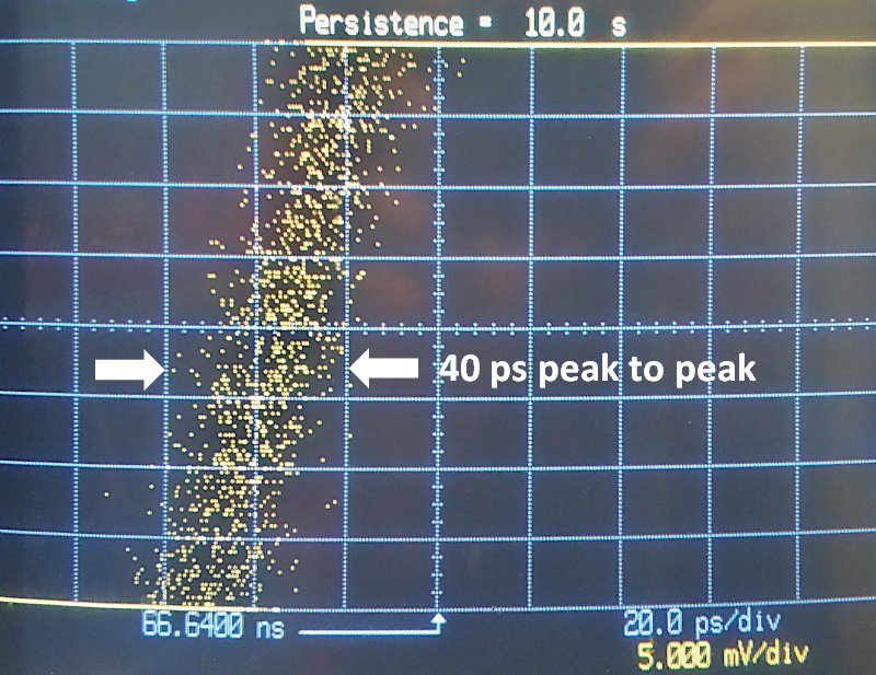
| Additive Jitter | 6.7 | ps RMS | |
| Trigger frequency range | 0.15 | Hz | Minimum |
| 5 | MHz | Maximum |
