Chassis
The SPI Rack chassis houses the modules and connects them via an integrated backplane. It can house up to twelve modules in twelve identical slots. The chassis connects the modules to a backplane which provides the power, digital communication and certain analog signals to each module. This chassis has been designed for a multitude of applications: both DC and RF modules, and isolated and non-isolated use cases. All while retaining backward compatibility with the IVVI Rack, more on that here.

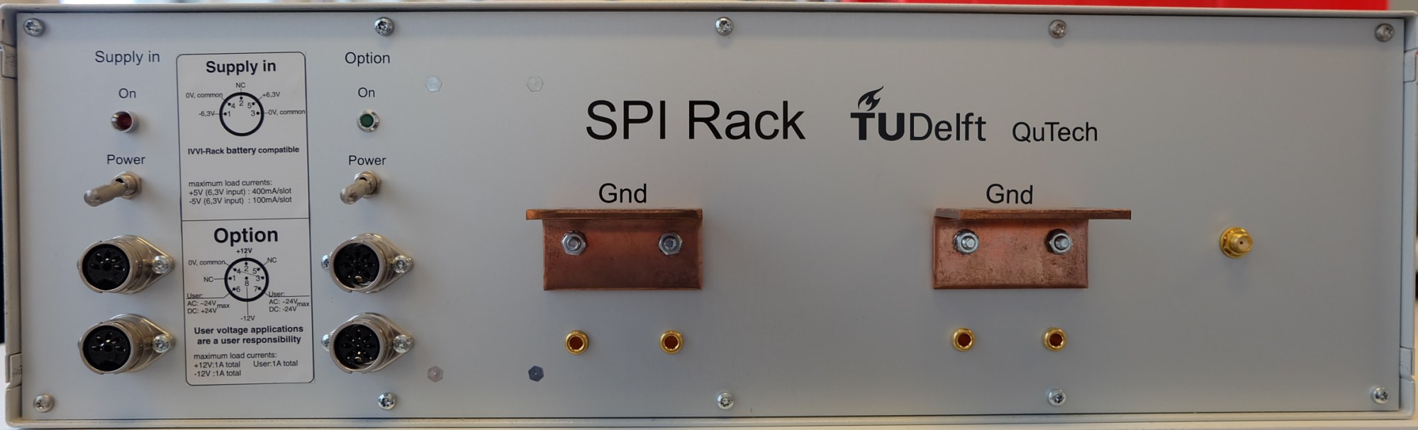
The back of the chassis contains two IVVI compatible battery connectors on the far left with associated power switch and LED. These connectors should be used with the normal batteries or power supply. The second column of connectors are for the optional voltages: ±12V and a user defined voltage. For more details see Power Supply. In the middle there are two copper grounding profiles. These are used to connected to the matrix rack, fridge, sample ground or any other object using braided copper cable. On the far right there is a SMA connector for the shared RF reference, which is used by certain RF modules. The maximum reference frequency is 200 MHz.
The figure below shows the backplane connections in schematic form. Each line and colour indicate a different function/connection:
SPI Bus All the digital communication happens via the SPI Bus. It connects to all the modules. Only one module can control the bus: the control module. All the other modules can only listen. No two controllers should be placed in one rack as this would give conflicts.
Digital Lines These are a couple of digital lines connected to each module. They could, for example, be used to trigger multiple modules at the same time. At the moment these are not used.
Power supply There are multiple power supply lines running through the backplane: the raw power supplies (±6V,±12V,±user voltage) and the regulated -5V are distributed to each module. The regulated 5V power is regulated in groups of 3 modules.
RF Reference The RF reference can be used by the RF modules to sync to other measurement equipment. The maximum reference frequency is 200 MHz.
Analog lines The analog lines are grouped per three modules and are used to create backwards compatibility with the IVVI modules. For more information on this, see the IVVI compatibility page.
