M2j - Low Noise Amplifier

Description
The M2j module is a low noise amplifier initially designed for use in reflectometry. It has been optimised for use with the F1d IQ Demodulator with a 40 MHz to 1.5 GHz frequency range. This is reflected in the gain flatness of M2j: within 3dB from 40 MHz to 1.4 GHz.
Below is a block diagram of the inner workings of the module. The first stages are two Low Noise Amplifiers (LNA). Following these is a variable attenuator (controlled by a DAC or a potentiometer) to allow for a 30+ dB output power tuning range. The output stage contains multiple 20dB power amplifiers to be able to reach a 20 dBm maximum output power. A level detector is placed near the output to notify the user that the amplifier is reaching its 1dB compression point.
The figure below shows the S21 at both minimum and maximum gain. Both curves within 3dB from 40 MHz to 1.5 GHz. Over the whole frequency span, the tuning range remains 35 dB.
Specifications
| Parameter | Value | Units | Conditions |
|---|---|---|---|
| Gain | 35 to 70 | dB | Within 3dB from: 40 MHz ≤ f ≤ 1200 MHz |
| Noise Figure | 1.3 | dB | At 70 dB gain |
| 5.7 | dB | At 35 dB gain | |
| P1dB | 20 | dBm | 1 dB Compression point |
| S11 | < 10 | dB | For 40 MHz ≤ f ≤ 2200 MHz |
| Spectral Purity | |||
| LED Clip Level | 18 | dBm | |
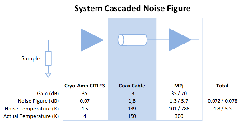
Cascaded Noise Figure
The noise figure of the M2j increases with a decreasing gain setting as seen in the specifications. Let’s look at the effect of this increased noise on the total setup. In the figure below we see a simplified setup consisting of a cryogenic amplifier, a coaxial cable running from 4K to room temperature and the M2j amplifier. The cryoamp numbers are based on the Caltech CITLF3 amplifier. From the figure we can see that the increase in noise of the M2j is negligible for the total system noise. It also shows the need for a cryogenic amplifier with high gain and a low noise figure: it determines the noise figure of the system.

