C1b - Isolated Controller

Description
The isolated controller consists of 2 parts: the C1b controller module and the C2 SPI Isolator box. In contrast to the C1; the signals, power and grounding from the PC are not connected to the SPI Rack. It is therefore the recommended controller for users who do DC measurements, as it doesn’t create any unwanted ground connections/loops. The figure below shows a block diagram of the setup.
The PC is connected to the C2 SPI Isolator box with a USB cable. This box contains the brain of the controller pair: the ARM microcontroller. The microcontroller interprets the incoming USB data and transmits this as SPI data towards the SPI Rack. Before it goes there, it first passes through a PCB which galvanically isolates the signals. The SPI Rack houses the C1b module which receives the incoming data and distributes it over the backplane. It is connected to the C2 SPI Isolator box with a standard Displayport cable. In the sections below we will take a more in depth look at both parts.
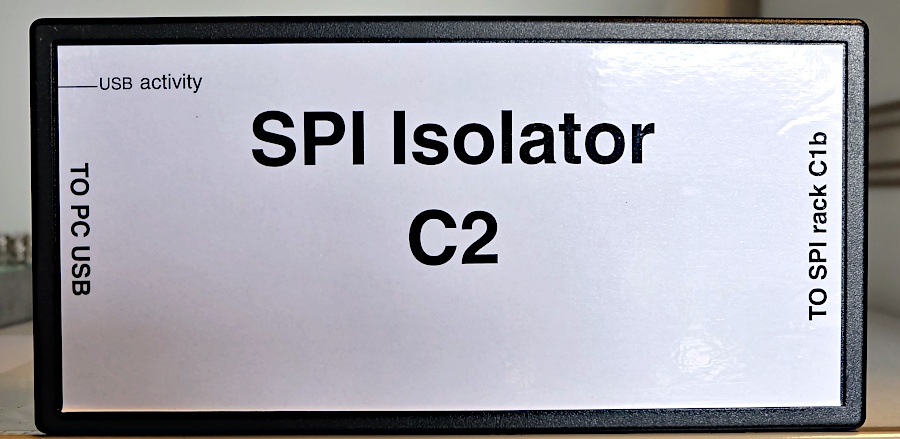
C2
Inside the C2 SPI Isolator box we find the same microcontroller as in the C1 module. From a user point of view, there is no difference in interfacing between the two. In reality they run different firmwares and perform the same tasks in different ways. A big difference with the C1 module is the addition of a PCB responsible for the galvanic isolation and the conversion to differential signaling. Below is a block diagram of the box.
The microcontroller in the box only acts as a go-between: at the moment of writing it contains no routines to control the modules by itself. All the data to the individual chips in the modules comes from the PC code. This allows for easy and fast development, at the expense of exact timing. If necessary, control routines could be added. The USB connection emulates a virtual serial/COM port on the PC. This provides easy interfacing from almost any programming language/development environment. If you’re running MacOS, Linux or Windows 10, there is no need to install drivers as the OS has them build in. For earlier versions of Windows, the drivers can be found in the GitHub repository here: https://github.com/mtiggelman/SPI-rack/raw/master/drivers.zip For more information on the software, see the software pages.

C1b
The C1b module does not contain any clocked logic, apart from when data is being written. Its main function is to route the incoming data from the C2 box to the correct module via the backplane. It does this with some simple logic inside the CPLD. In addition to this, it also contains a temperature sensor and a two channel ADC to measure the raw battery voltage. The ADC can be used by the user to monitor the batteries to see when they need replacement or to monitor if the gyrator is still functioning. The temperature sensor could be used for example to correlated measurements with temperature fluctuations, like a day/night rhythm.
Firmware Version
The table below shows the firmware versions for the microcontroller in the C2 and the changes with each version.
| Version Number | Changes |
|---|---|
| v1.5 | Added software SPI for lower SPI clock speeds, used in the U2 module Add firmware version readout over USB Fixed S5k writing error |
| v1.4 | Fixed chip select setting problem (problem with module number > 3) |
| v1.3 | Changed write to not wait for read back |
| v1.2 | Added SPI write lock on Supply Monitor interrupt |
| v1.1 | Added SPI write lock at Power On Reset |
| v1.0 | Initial version, for prototype C1 & C2 |


