Power Supply
The back of the SPI Rack contains the power connectors. There are two incompatible types of connectors for different applications. The first column of connectors is the mandatory supply input. It uses the same battery connector as on the IVVI Rack. This should always be connected to a power source, otherwise the rack will not function. Depending on the use case, this could be either a battery, preferably as a set with a gyrator, or a modified lab supply. More on this below.
The second column of connectors are the optional power supplies. There are two voltages defined here: a ±12V and a user-defined voltage. The ±12V can be supplied either from a battery combination or a lab power supply. The user-defined voltage can be anything within boundaries: AC not over 24 Volts, DC not over ±24 Volts and the current should not exceed 1 Ampere.
Below is an image of the back of the SPI Rack with the Connectors, switches and information sticker. Both columns of connectors have their own power switch with corresponding LED. If the LED is on, the power is on, regardless of the LED colour.

Isolated SPI Rack
If the SPI Rack will be used for sensitive DC measurements, it should be isolated from the mains power and ground. To achieve this, both an isolated controller and an isolated power supply are needed. The option of a modified lab power supply is unsuitable in this case. For details on the isolated controller see C1b.
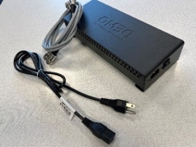
The isolated power supply is a battery unit containing two 6V lead acid batteries placed in a metal box with a capacity of 12AH. The SPI Racks have two connectors for the batteries to enable uninterrupted battery change. The metal battery-enclosures are used in combination with shielded cables. These enclosures are connected to sample-ground and thus mounting them should be done free of connections to mains ground. The fuses on the battery units prevent excessive currents (>6A) in case of short circuit. For more information on the batteries click here. See the image below for a picture of a battery unit.

Gyrator
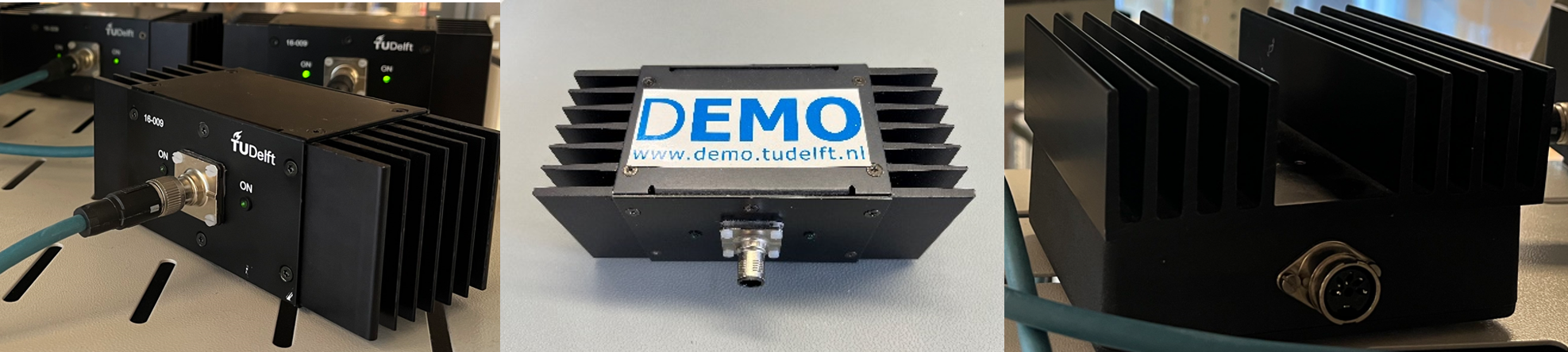
A recommended alternative to swapping batteries is to use a battery in parallel with a gyrator. This includes the gyrator unit together with a power supply (also called 'gyrator supply' in thsi context) connected to mains voltage. This set-up will power the SPI Rack and keeps the battery topped up. This is the only way in which the SPI Rack and battery can be connected directly to the mains! The diagram below shows the different parts and how it should be connected.
 The first device is the power supply (on the right in the image below). It is a linear power supply with a built-in mains filter and low capacitive coupling. Its metal casing is connected to mains-ground, so do NOT put this on the same 19 inch rack as the SPI rack is housed in! The regulated output of the supply runs through a shielded cable with a ferrite core around it (to block high frequency noise) to the gyrator unit (left on the image below). Inside the gyrator is a common mode choke and active circuitry that mimics a very large inductor (40 Henry) on every power lead. This prevents interference signals (like 50 Hz) from getting to the SPI Rack.

The original set of power supply and gyrator is shown in the picture above. This set was initially designed for the IVVI, and can deliver up to 0.3A on both positive and negative supplies. There are other sets available with newer design for the power supply and gyrator, which are intended for more power-hungry applications on an SPI rack (such as some RF set-ups, and others) which can deliver up to 1.5A on both supplies. The table below shows the available sets, their possible components, and order of connectivity:
| Set Name | Power Supplies | Supply-to-Gyrator Cable | Gyrators | Gyrator-to-Battery and Battery-to-Rack Cable |
|---|---|---|---|---|
| IVVI Power Supply and IVVI gyrators |
 |

|  |

|
| SPI Power Supply model 2A and SPI gyrator |
 |
 |
 |
|
| SPI Power Supply model 2B and SPI gyrator |
 |
|
|
|
Note that within QuTech we usually prefer Power Supply model 2A. While it is uncertified per industry standards, it was measured to offer better noise suppression compared to model 2B.
Grounding: The rack itself AND the batteries are connected to sample ground! Only the isolated BNC’s are connected to (usually) line-powered equipment and thus to mains-ground. Mounting the rack in a metal frame together with line-powered equipment means: connecting sample-ground to mains-ground. This also applies to the gyrator power supply. Although sample-ground should NOT be left floating, the user should be aware of the location where connection to ground is made and multiple connections are not advisable.
Non-isolated SPI Rack
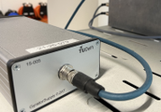
If the SPI Rack will be used for RF applications it is not necessary to have an isolated power supply and controller (C1). A lot of the RF modules also draw considerably more power, which would lead to a quick battery drain. Therefore a modified lab power supply can be used. A connector has been added to the back to allow for use of the standard battery cables and the output voltages are preset (cannot be changed). See the image below for a picture of the power supply.


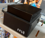
Occasionally modified power supplies break down. This malfunction might cause an extended period of over-voltage, which could damage the SPI electronics. Modules and rack might become unstable until repaired or replaced. To avoid this issue, it is advised to use a voltage protection box for set-ups utilizing the modified supplies. This device sits between the TENMA supply and the load. The image below shows the supply protection box.

The box is designed for a modified Tenma supply which has an added back-side connector for supply cable. If you happen to use an unmodified TENMA powersupply (missing the cable connector) mention this in your order, so a custom solution can be made.