Why different connectors?
Many coaxial connector types are available in the audio, video, digital, RF and microwave industries, each designed for a specific purpose and application. Much of the development of the smaller connectors that perform well into the GHz and millimeter wave range has been conducted by test equipment measurement companies. One of their considerations is the number of connect-disconnect cycles that a connector pair can withstand while still performing as expected.
Why different sizes and frequencies?
The frequency range of any connector is limited by the excitation of the first circular waveguide propagation mode in the coaxial structure. Decreasing the diameter of the outer conductor increases the highest usable frequency. Filling the airspace with dielectric lowers the highest frequency and increases losses. The mating process typically changes the geometry of the mating surfaces and resistance loss at those interfaces as well as geometric changes result in variation of impedance and loss.
Some RF connectors are sexless (such as the HP/Amphenol APC-7 and the General Radio GR874 and GR900BT). Most connectors have female structures with slotted fingers that introduce a small inductance. The fingers accommodate tolerance variations, but reduce repeatability and may ultimately break after 1000 connections. There are slotless versions of connectors available, but they are, for the most part, relegated to instrument interfaces. Slotless female connectors are very difficult to clean and require very careful connection and disconnection.
Connecting and Disconnecting
RF and microwave connectors are precision-made parts, and can be easily damaged by mistreatment. You should start with all connector surfaces as clean as possible, using a solvent such as alcohol or a special-pupose cleaner to do the job. Use as little as you can, and in no event contact dielectric spacers or resistive materials (as used in loads) with the solvent, since these can be irreparably damaged by the solvent. As a general rule, if the connectors have threaded sleeves, you should rotate these to tighten, leaving the rest of the connector (and cable) stationary. If other parts of the connector are twisted while tightening or loosening, damage can easily occur.
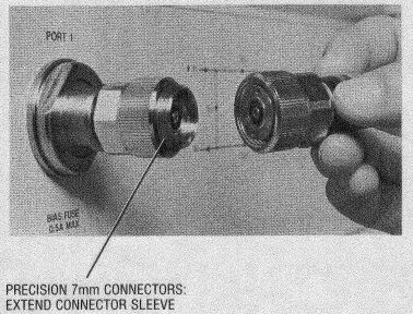
Connecting 7 mm connectors is somewhat different, and perhaps counterintuitive. These are sexless connectors, and the mating surfaces mount flush and are held together by a single rotating sleeve. The mating sequence is:
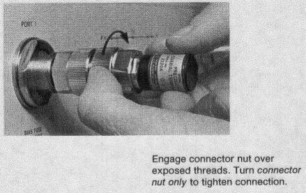
1. Each connector has an outside rotating sleeve. On one connector, rotate the outer sleeve so that the threaded connector sleeve extends completely out from the outer sleeve. Do this on any fixed-mounted connectors, such as those on the test ports of a network analyzer. On the other connector, rotate the outer sleeve so that the threaded connector sleeve recedes completely into the outer sleeve.2. Mate the surfaces flush and rotate the forward sleeve to engage the threads of the other connector.
3. Complete connection is made when the forward rotating sleeve is tight and the other sleeve is loose.
Caution: one sleeve must be loose. Tightening down both sleeves
can cause connector damage.
| Connector Type | Other names (or mates with) | Female | Male | Maximum Frequency (GHz) | Notes |
| Phone plugs and jacks | TS, TRS | 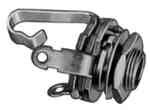 |
 |
10-4 or less | Ever see those old telephone switchboards with hundreds of jacks and patch cords and plugs? Those are phone jacks and plugs, also known as TS (Tip-Sleeve) for two-conductor connections, or TRS (Tip-Ring-Sleeve) for three-conductor connections. They are now used widely with musical instruments and audio equipment. The phone plug is the male connector, a phone jack is the female connector. The standard diameter of the plug is 0.25", but many smaller sizes are available as well. These are really only suitable for audio frequencies. |
| RCA | Phono plugs and jacks |  |
 |
0.01 | A round, press-on connector commonly used for consumer-grade audio and composite video connections. In most recent home stereo equipment, the jacks are color-coded as follows: red (audio-Right), black or white (audio-Left) and yellow (composite video). Generally not a constant characteristic impedance connector. |
| UHF | PL-259 (male), SO-239 (female) |  |
 |
0.3 or less | The UHF type connector saw its conception in the early
1930's, a time when VHF/UHF technology was quite new. The forefathers of
VHF were in many cases Amateur radio experimenters, most with Engineering
and technical backgrounds. They began experimenting and working the VHF
frontier around 1926. Soon thereafter research into FM radio and
Television began and out of this era came the then named UHF connector.
Manufactures of UHF plugs and receptors all state that this type connector
are of generally non-constant (characteristic) impedance and are
suitable for use up to 200 or 300 MHz only, depending on production
quality. They also state that the UHF connector can be used up to 500 MHz
with a cautionary note of reduced performance.
The so named UHF connector from the past is not really suitable for use above 300 MHz at all. Perhaps the exception to this would be when a cheap and rugged system is required where loss and good signal to noise ratio is of little concern. However, even for frequencies as low as 144 MHz, if low loss and good signal to noise ratio are very desirable, the use of UHF type connectors is not recommended. The UHF connector still has a place in many applications where a robust but economical RF connector is required, but for serious applications its use should be limited to below 100 Mhz. The N type is far superior in performance, and it should also be noted the BNC type connector is similar in performance to the N type, but has the disadvantage of being less rugged. |
| F | Video | 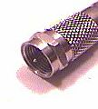 |
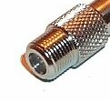 |
0.25 to 1 | The “F” series connectors are primarily utilized in television cable and antenna applications. Normally these are used at 75 ohm characteristic impedance. 3/8-32 coupling thread is standard, but push-on designs are also available. |
| BNC | 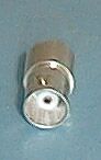 |
 |
2 or higher | The "Bayonet Neil-Concelman" or "Bayonet Navy Connector" or "Baby Neil Connector", depending on the information source. Karl W. Concelman is believed to have created the "C" connector. The BNC was designed for military use and has gained wide acceptance in video and RF applications to 2 GHz. The BNC uses a slotted outer conductor and some plastic dielectric on each gender connector. This dielectric causes increasing losses at higher frequencies. Above 4 GHz, the slots may radiate signals, so the connector is usable, but not necessarily mechanically stable up to about 10 GHz. Both 50 ohm and 75 ohm versions are available. | |
| TNC |  |
 |
2 or higher | A threaded version of the BNC connector. It helps resolve leakage and geometric stability problems, permitting applications up to 12 GHz. The specifications for N, BNC and TNC connectors are found in MIL-C-39012. There are special "extended frequency" versions of the TNC that adhere to the IEC 169-17 specification for operation to 11 GHz or 16 GHz, and the IEC 169-26 specificaion that operate mode-free to 18 Ghz (but with significant losses). The TNC connector is in wide use in cellular telephone RF/antenna connections. Because the mating geometries are compatible with the N connector, it is possible to temporarily mate some gender combinations of BNC and N. This is not a recommended use because the connection is not mechanically stable, and there will be significant impedance changes at the interface. | |
| 7/16 DIN | 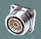 |
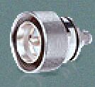 |
7.5 | This relatively new connector is finding popularity as an interconnect in cellular and other so called "wireless" applications, especially on towers. The primary advantage it has over N type connectors is that it uses a wrench to tighten. It is rated to 7.5 Ghz, uses rubber gaskets and silver or gold plate. | |
| GR874 | General Radio (to old-timers, anyway), G874 |  |
same | 8.5 | GR874 connectors are hermaphroditic, 50-ohm impedance connectors with a slide-on interface that has been a standard for many years on a wide variety of test equipment, due to its good electrical characteristics and ease of mating. These connectors sometimes come with a locking interface for added mechanical security where needed. Locking and non-locking interfaces are intermateable. |
| GR900BT | 14 mm, MPC14 |  |
same | 8.5 | These sexless (hermaphrodite) connectors are often used in highly critical laboratory applications at frequencies up to 8.5 GHz. |
| C |  |
12 | C connectors are medium-size, 50-ohm impedance connectors with two-stud bayonet coupling and good power handling capability, particularly those connectors noted as high-voltage types. These are similar in size to type N connectors, however, they are bayonet locking. The C series uses a teflon dielectric for its interface. The dielectric overlap enables better voltage handling capabilities. The bayonet coupling does not perform well electrically during vibration. | ||
| Type N | 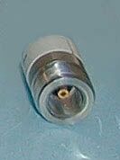 |
 |
12 or more | The Type N 50 ohm connector was designed in the 1940s for military systems operating below 5 GHz. One resource identifies the origin of the name as meaning "Navy". Several other sources attribute it to Mr. Paul Neil, an RF engineer at Bell Labs. The Type N uses an internal gasket to seal out the environment, and is hand tightened. There is an air gap between center and outer conductor. In the 1960s, improvements pushed performance to 12 GHz and later, mode-free, to 18 GHz. Hewlett Packard, Kings, Amphenol, and others offer some products with slotless type-N outer conductors for improved performance to 18 GHz. Type-N connectors follow the military standard MIL-C-39012. Even the best specialized type-N connectors will begin to mode around 20 GHz, producing unpredictable results if used at that frequency or higher. A 75 ohm version, with a reduced center pin is available and in wide use by the cable-TV industry. | |
| SMA | 3.5 mm or APC-3.5, WSMA, 2.92 mm, K |  |
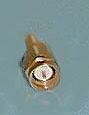 |
12 or more | The SMA (Subminiature A) connector was designed by Bendix
Scintilla Corporation and is one of the most commonly used RF/microwave
connectors. It is intended for use on semi-rigid cables and in components
which are connected infrequently. It takes the cable dielectric directly
to the interface without air gaps. A few hundred interconnect cycles are
possible if performed carefully. Care should be taken to join connectors
straight-on. Prior to making a connection it is wise to inspect the female
end to assure that the center socket is in good condition (fingers not
bent or missing).
A standard SMA connector is designed for interconnects to 12.4 GHz. Fortunately, a good SMA is useable to 18 GHz in most cables, and if well constructed with greater loss and lower return loss to 24 GHz. Most SMA connectors have higher reflection coefficients than other connectors available for use to 24 GHz because of the difficulty to anchor the dielectric support. Some manufacturers rate a special high quality version of an SMA that meets SMA standards as high as 26.5 GHz (The Johnson Field Replacable SMA goes to 26.5 GHz, and the M/A-Com OSM extended frequency series goes to 27 GHz). Because an SMA with such quality can be repeatably manufactured, you will often see test equipment and components rated to exactly 26.5 GHz with SMA connectors as the primary interconnect. "SMA" connectors rated for frequencies higher than 27 GHz are really following other standards and are made to be compatible with the SMA geometries to allow mating with SMA. So called "precision SMA" connectors are available with a variety of designators (e. g., 3.5 & 2.92 mm). When two SMA compatible connectors of different ratings are coupled, it is very likely that the performance of the lesser connector will prevail. Be advised that when mating a male SMA to a female "Precision SMA", to be sure that the SMA male is of professional manufacture, and to insert the male straight-on. If there is any doubt, it is wise to invest in an SMA Connector Gauge, and guage the SMA male prior to mating. This advice does not apply to the connection of an SMA female to a 3.5 or 2.9 male. Such connections do need to be made with care and straight-on. |
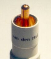
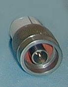
| APC-7 | 7 mm | 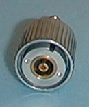 |
same | 18 | The APC-7 (Amphenol Precision Connector - 7 mm) offers the lowest reflection coefficient and most repeatable measurement of all 18 GHz connectors. Development of this connector was a joint effort between HP and Amphenol which began in the early 1960s. This is a sexless (hermaphrodite) design and is the preferred connector for the most demanding applications, notably metrology and calibration. These connectors are designed to perform repeatably for thousands of interconnect cycles as long as the mating surfaces are kept clean. You will find these connectors on the front of some network analyzers. |
| 2.4mm |  |
 |
50 | The 2.4 mm connector was developed by HP, Amphenol and M/A-COM for use to 50 GHz (the first waveguide mode is reached at 52 GHz). M/A-Com refers to it as OS-2.4 (OS-50). This design eliminates the fragility of the SMA and 2.92-mm connectors by increasing the outer wall thickness and strengthening the female fingers. The inside of the outer conductor is 2.4 mm in diameter, and the outside is 4.7 mm. Because they are not mechanically compatible with SMA, 3.5-mm and 2.92-mm, precision adapters are required in order to mate to those types. (This family is not directly matable with the SMA family.) The 2.4-mm product is offered in three quality grades; general purpose, instrument, and metrology. General purpose grade is intended for economy use on components, cables and microstrip, where limited connections and low repeatability is acceptable. The higher grades are appropriate for their respective applications. |
Torque for tightening connectors
| Connector type | Torque lb-inch (N-cm) | Comment |
| Precision 7mm | 12 (136) | Finger tight is acceptable |
| Precision 3.5 mm & 2.92 mm | 8 (90) | When connecting SMA to 3.5 use torque for male connector |
| SMA | 5 (56) | When connecting SMA to 3.5 use torque for male connector |
| Type N | 12 (136) | Finger tight is acceptable |
This page is based on material from
http://www.wa1mba.org/rfconn.htm, http://minyos.its.rmit.edu.au/~rmmca/pl259tst.html,
http://www.gohts.com/techwire/coax.html,
http://www.tm.agilent.com/, http://www.vandenhul.com/other/c-connec.htm,
http://www.connectronicsinc.com/,
http://www.mackie.com/TechSupport/Glossary/M-Z.asp,
http://www.deltarf.com/ and http://www.maurymw.com/,
as well as from:
C. A. Harper (ed.), Handbook of Wiring, Cabling, and Interconnecting for
Electronics. New York: McGraw-Hill, 1972.
Microwave Connector
Care, Manual Part No. 08510-90064, Hewlett-Packard, April 1986.
The
ARRL UHF/Microwave Experimenter's Manual. Newington, CT: American Radio
Relay League, 1990.