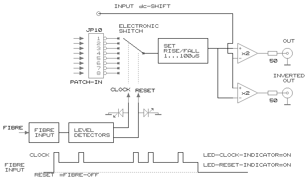
This is a module generating complex pulse patterns (max. 8 segments L0..L7) with very high dc-accuracy and adjustable slope. It is actually an analog switch and bufferamp controlled by an external clock (fibre).
By connecting DACs each segment can be set and the unit can be used for fast (ms..us) gate sequencing. The module can also be used as a multiplexer for lock-in type of measurements.

A fibre emitter can be connected to a commercial generator capable of generating at least +3V in 50ohm. The emitter is powered by the signal itself.
The fibre pulse is the clock on which the switch advances (L0>L1>L2 etc).
The fibre signal can also be used to reset the switch to position L0.
a simplified diagram of the module:

If only 2 segments are needed an standard pulse generator is sufficient. The module will toggle between L0 and L1 and act as a 2 level pulse generator.
If a continuous 8 segment waveform is needed it is also possible to use a standard pulse generator with dc-offset. The offset level is set to 50% and the unit will not reset but cycle:L0-L1...-L7-L0-L1... etc.
The dc-levels can be set by monitoring the clock-LED and reset-LED on the front
If the user also wants to control the length of each segment and the number of segments a socalled arbitrary waveform generator is needed, this can be a lowfrequency-type <1kEuro . If the fibre-lightlevel is zero, the unit resets (indicated by an LED on the front). Clocking is done by toggling the lightlevel between 50 and 100%. The dc-levels can be set by monitoring the clock-LED and reset-LED on the front
This way (using the reset) the number of segments can be chosen from 2 to 8.
The rise/fall time can be set from 1uS to 100uS by a potmeter or a DAC-control signal. This makes it possible to minimise transients for a given segment clock speed.
The offset can also be set via a DAC.
The 50 ohm outputs drive 4V (2V in 50 ohm). To get high accuracy with minimal crosstalk it is advised to terminate both (complementary) outputs with 50 ohm if one uses only one output to drive 50 ohm loads.
This is actually the main reason for the existance of the complementary outputs.
Other uses of the S5e:
Creating a 50ohm output for a dc/ac source (DAC, Vsource) No fibre needed, input on mcx L0
Creating a differential output for a dc/ac source. No fibre needed, input on mcx L0
Creating a "bias-tee" like function adding dc: (DAC on the offset input) and ac: segment DACs (or ISO-amp, no fibre needed)
Stepping rapidly through a set of preset DACvalues while triggering measurements on each value
For differential lock-in type of measurements the module has a high precision analog inverter creating an exact inverted value
of what is applied on the L0 front mcx. It is then possible to toggle between these 2 opposite values
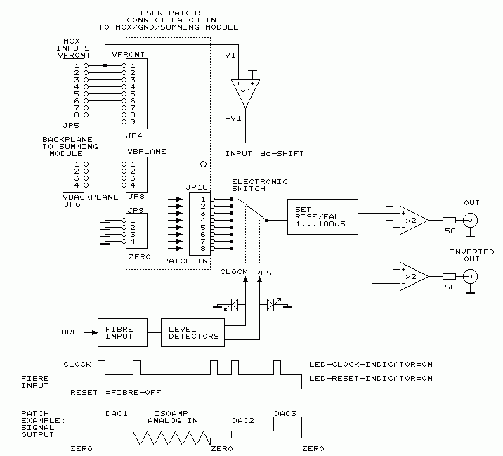
The 8 mcx front-connectors (L0..L7) are default connected to segment 0..7.
The user can open the module and patch other schemes using the user patch area
locations patch jumpers on board
picture of circuit board
sources are:
MCX inputs from front (JP4 pin 1..8)
ground pins (JP9)
backplane control lines from the summing module (JP6)
The precision analog inverter output (JP4 pin 9)
destinations are:
The switch segment inputs 0..7 (JP10)
The dc-offset input (JP7)
The rise/fall time control (JP3)
a simplified circuit of the module:
