(picture of prototype front, new versions have no charge/power switch)
This module is designed as a set of postamps for the D5(DACmodule) to provide max. +/-12V control of gates
In and output are default on the front-panel (mcx connectors) DAC-outputs are connected from the S2 module front to the S1f inputs using mcx-mcx cables.
As an option it is possible to use it as a source and control up to 4 amps via the back-plane (routing inside S2module)
The unit has 2 internal 9V batteries to extend the +/-5V rack-supply to +/-14V. Battery life is > 1year. If the batteries run empty the module still works but max voltage swing will decrease and finally limits to approx +/- 4V.
The battery check switch only functions when the unit is in a powered rack.
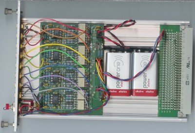
Replacing of the batteries can be done by the user, remove the cover (max. 6 screws) and on the board 2 rectangular 9V batteries are placed with sticky tape..(the batteries should not touch metal parts)
(see picture below)
The battery check function only works when placed in a powered rack
description of the first version (can be recognised by the charge/power switch on the front):
The unit has 2 internal rechargeable batteries to extend the +/-5V rack-supply to +/-14V. Battery life is >200 hrs. If the batteries run empty the module still works but max voltage swing will be approx +/- 4V.
Switch to "charge" when rack-supply is on charges, otherwise it just saves battery life.
Pushing the "batt.check" is possible during operation, but if the batteries are already partly down then there might be a small drop in max. output voltage during check.
Replacing of the batteries can be done by the user, remove the cover (max. 6 screws) and on the board 2 rectangular 9V RECHARGEABLE batteries are placed with sticky tape..
(in case of "emergency" standard 9V also work, but cannot be charged)
S1F module inside showing batteries:
