This module is designed to measure currents with a noisefloor down to 5fA/sqrtHz(@1G V/A). It is also optimised to send very little energy to the sample. For that reason it's input resistance is not "as low as possible" but fixed at a function of the [V/A] setting (see calculation below).
There is a postgain switch [x100ac x1 x100dc] giving a max total output of 100G V/A (using x100dc). For bipolair Log-option: see end-of-page
When doing noise measurements as a function of dc-current the [x100ac] makes it possible to amplify the noise while maintaining a large dc-sweep range.
The postgain can also be used to obtain a lower Rin/ higher speed at high V/A settings. Example: 1G V/A could be exchanged for 10M V/A with postgain [x100dc] (you pay with higher noise).
The ground-lift switch [gnd-lift] solves problems with thermovoltages that are usually present in cryogenic setups. The zero reference pin(2) can be connected to a cold-ground-wire when in the [gnd-lift] mode.
In the [gnd] mode pin2 is connected to (warm)ground inside the module, identical to the M1 module.
2=gnd means that pin 2 is internally connected to ground=the rack This is the way that most iv-converters are hooked up.
2=ref-in means that you can (and should) connect pin 2 to a reference ground that can have a difference dc-level (up to some 100mV) e.g. a wire from cold-ground inside the fridge. This helps to remove excess offset by thermovoltages.
Usual procedure to determine offset voltage: If you put your voltagebias on 0V there should be no current, otherwise tune it to a value where I=0, the voltage that you have now is the offsetvoltage in the system. You can compensate by taking this into account.
Rin calculation
Rinput is set at: 2kohm + 1E-3 * [V/A] for [low-Noise]
and: 2 kohm+1E-4 * [V/A] for [low-Rin]. Example: at 100M V/A the input resistance is 102kohm @[low-Noise] or 12kohm @[low-Rin]. These values are accurate within 1% so a possible voltage drop can be subtracted in the data.
OPTION: "Log" function:
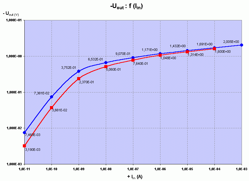
To be able to measure curves with very high dynamic range (> 8decades) A simple inaccurate bipolair log function is added.
On the lowest current range response speed goes down to a few Hertz
Measured IV-curve is shown (blue trace is at 20 celcius, red at 35 celcius)
To be correct: it is a LOG function in parallel to a 1Gohm(option 10Gohm) resistor to have more stable results
and faster speed at low current. As a result the higher currents >1nA are compressed via a true LOG function

Log, time domain:
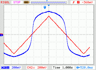
This shows a time domain picture for the log response(blue) on a 10nA triangular wave(red) at 1 sec/div:
